
 See larger image
 Leave Messages

 Products Detail
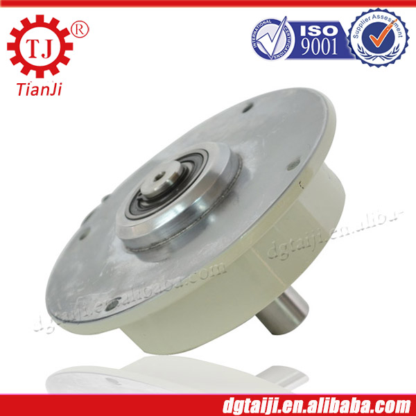
Structure and working principle
The magnetic powder clutch is composed of active rotor(input shaft), driven rotor (output shaft) and Yoke with excitation coil. The three parts are resembled against the concentric part and form a system which can rotate relatively. The annular gap between active rotor and driven rotors is full of alloy powder which has high permeability.
The magnetic powder will be in the state of loose when the current do not pass the excitation coil. The magnetic powder will be thrown on the inner wall of active rotor. In this case, there will not exist the interaction force between the active and driven rotor. Because the magnetic powder clutch is in the state of separation, no torque transmission exists.
The magnetic powder in the working chamber will link in a link state under the action of the magnetic flux generated from the Yoke when the current pass the excitation coil. The magnetic powder clutch can transfer torque relying on the shear force generated from magnetic chain and the friction generated from the magnetic powder and working face. in this case, the magnetic powder clutch is in the state of combination.
When the current is cut off, the magnetic flux will disappear with the disappearance of the magnetizing current, the magnetic powder will be in the state of loose under the action of gravity again, and will be thrown on the inner wall of active rotor under the action of the centrifugal force. In this case, the magnetic powder clutch will be in the state of separation again.
The magnetic powder clutch and brake have the same principle; the magnetic powder brake will form as long as the driven rotor of the magnetic powder clutch is fixed.
Model TJ-POD-C | 0.05KG | 0.1 KG | 0.2KG | 0.5 KG | |
Rated torque (N-m) | 0.5 | 1.0 | 2.0 | 5.0 | |
Current (A) | 0.35 | 0.42 | 0.5 | 0.6 | |
Allowable rational speed (r/min) | 0.4 | 0.54 | 0.96 | 1.3 | |
Power (W) | 1800 | ||||
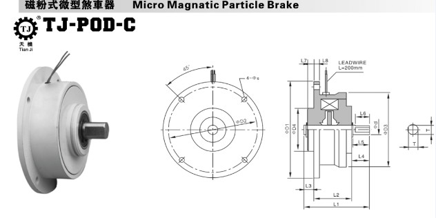
Outline dimension
| D1 | 70 | 76 | 90 | 108 |
D2 | 60 | 66 | 80 | 95 | |
D3 | 50 | 56 | 70 | 82 | |
D4(g7) | 24 | 30 | 40 | 44 | |
d(g7) | 5 | 7 | 9 | 15 | |
L1 | 45 | 50 | 59 | 66 | |
L2 | 29 | 30 | 34 | 36 | |
L3 | 5 | 7 | 9 | 11 | |
L4 | 11 | 13 | 16 | 19 | |
L5 | 10 | 12.2 | 15 | 18 | |
L6 | 9 | 10 | 13 | 16 | |
L7 | 3 | 4 | 6 | 8 | |
L8 | 4 | 4 | 5 | 5 | |
S | 4.5 | 4.5 | 4.5 | 6 | |
T | 4.5 | 6.5 | 8.5 | 14 | |
Magnetic Powder Brake Featured advantages
1. Fast response. Dry design means instant reaction to commands.
2. Durability. Excellent heat dissipation and quality materials mean long life, even under high frequency and high performance conditions.
3. Easy to install and maintain. Sealed bearing race eliminates the need for removal of the center core. No dust brush is needed, and operation is simper and easier.
4. No adjustment of the motor. The motor is designed so that it does not need adjustment of the friction surface, and once it is installed only very minor adjustments are needed.
5. Sure motion. One-piece plate will not slip even under the strongest vibration for longer life.
6. Adjustable torque. Torque levels can be increased or decreased by changing the current, making it suitable for a variety of applications.
Application
Due to the features of the magnetic powder clutch and brake, they have been widely used in paper making, printing ,
plastic items, rubber industry, textile industry, printing and dyeing, wire and cable, metallurgy industry and tension contro
l of winding and unwinding in roll material processing industry.
Related Products


-

-

-

Automatic Pressure Control For Water Pump,Magnetic Powder Brake Water Pump Controller
-

Magnetic Powder Brake For Industrial With Single-Shaft Magnetic Powder Brake
-

DC24V Micro Magnetic Powder Brake For Industrial Printing Machinery
-

-

High quality Uniaxial China Supply PVC Label Printer Magnetic Particle Brake
-

Tianji Brand Direct factory Supply Super Quality 6Nm~400Nm Magnetic Powder Brake In China

